Benefits at a glance
- Very large grip range
- Rational fastening system – one lockbolt covers a very large area of installation
- Compensates for extensive differences in wall thickness
- Pin tip breaks off inside the collar (steel version)
- No protruding pin tip, no sharp edges (steel version)
- High clamp force
- Installation steps make for safe build-up of clamp force
- Constant clamp force/preload
- Vibration resistant
- No heat exposure around the joint
- No warping
- No refinishing required around the joint
- No surface damage on components
- Visual inspection
- Installation can be checked using process monitoring
- Maintenance-free
- Quick and easy installation
Installation steps
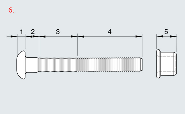
- Select lockbolts based on the specified requirements as well as the clamping thicknesses available on-site (sum total of all wall thick- nesses to be installed)
- Select the installation tool, incl. pulling head that matches the lock- bolts to be installed (for details, see “Overview – Lockbolts” in the “Tools for Lockbolts” catalogue)
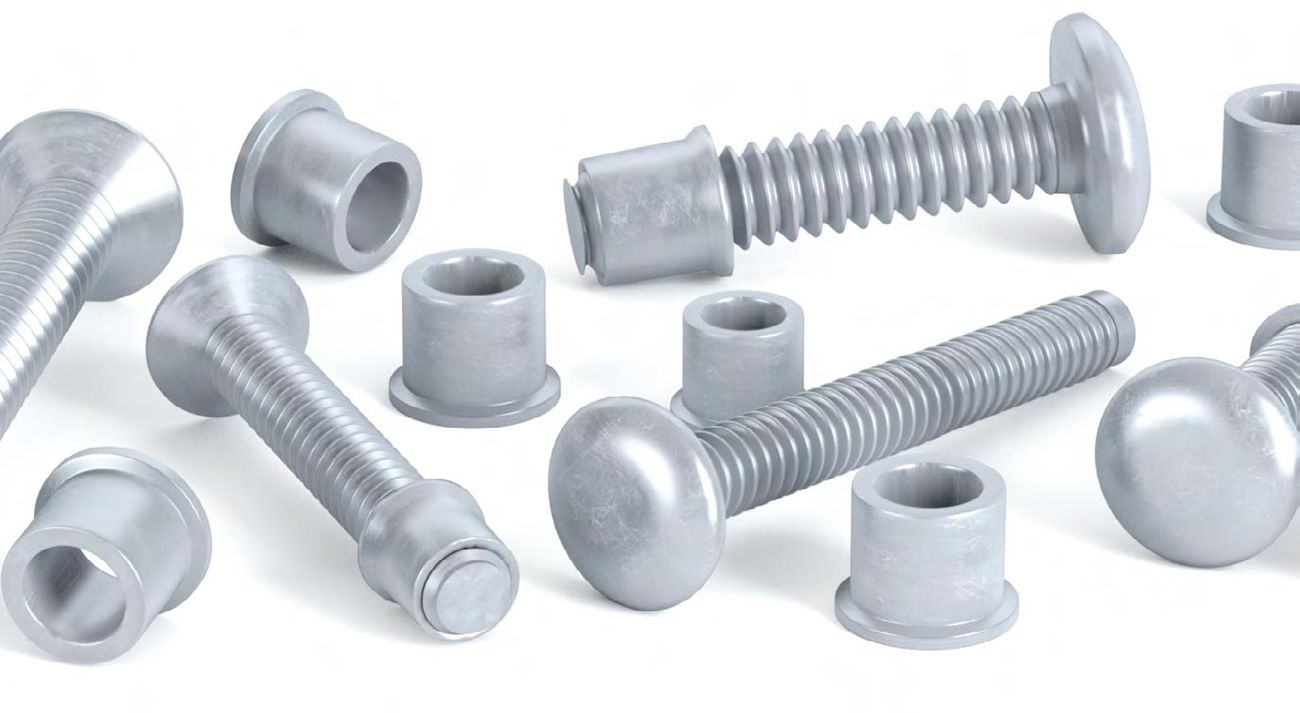
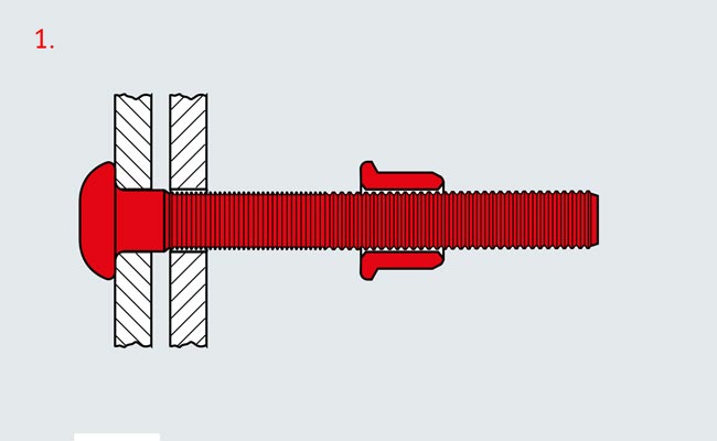
- Insert the bolt into both through- holes on the components and, with the chamfer aligned to the end of the bolt, slide the collar over the lockbolt. (Fig. 1)
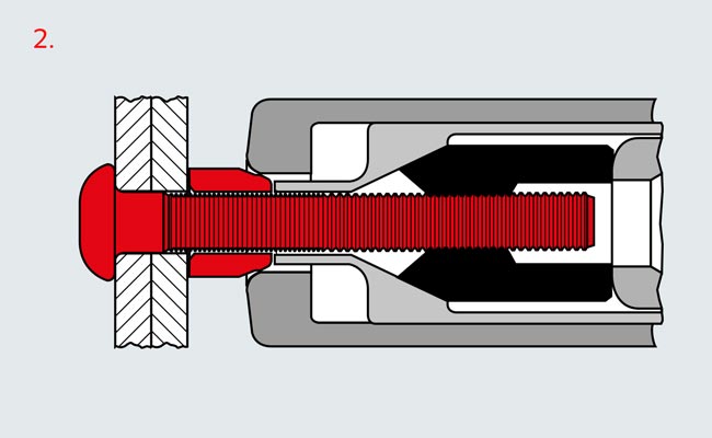
- Fully press the installation tool with attached pulling head against the collar while securing the pin in place from the opposite side to prevent it from being poked out. (Fig. 2)
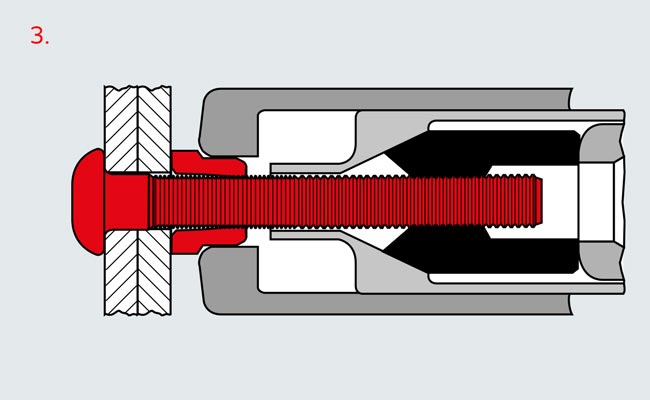
- Press the trigger on the installa- tion tool. The jaws then grip into the grooves on the pin tail and tug at the pin. The pulling head sleeve presses up against the components and the resulting clamp force pushes them together. (Fig. 3)
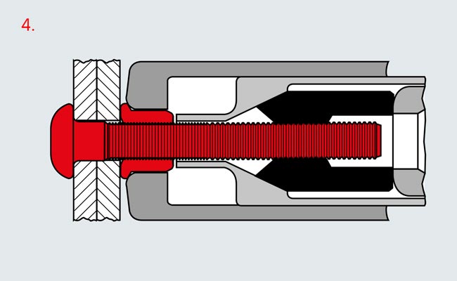
- As the tool continues to pull, the pulling head sleeve slides over the collar. (Fig. 4) This reduces the ex- ternal diameter of the collar. The compressed material slides into the locking grooves of the bolt to form the desired positive fit. As the front side of the sleeve elonga- tes, it is pushed up against the component to create the desired preload where the parts connect.
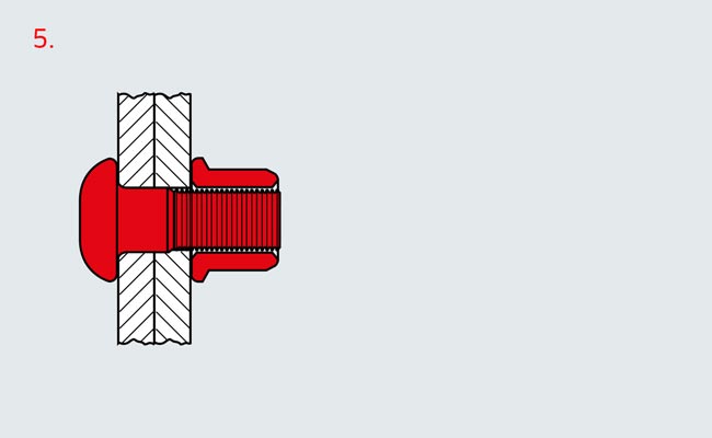
- The tool will continue to pull until the lockbolt's breakload is achie- ved, causing the tip of the bolt (pulling head) to snap off at the end of the collar (steel version). Installation is now complete. (Fig. 5)
